Simulation of Soft-Open-Point devices for Power Distribution Networks
Project Brief
During my BEng at the University of Aberdeen, I undertook a final year project focused on simulating in Simulink & MATLAB Soft-Open-Point back to back voltage source converter devices. Intended to connect distributed Scottish renewables with National Grid infrastructure, the project also covered a review of the economic and environmental aspects of such installations, determining how their application aides the transition to net zero.
Throughout this page a brief discussion of the simulation work is carried out, and several images of Simulink designed VSCs are included, this project is not currently being examined for further research or work privately. You may download a copy of the submitted University of Aberdeen thesis at the bottom of this page, for any questions please contact Joshua Mills.
What is a Soft-Open-Point voltage converter?
A soft-open-point, using a back-to-back voltage converter, is a power-electronics device that replaces the traditional mechanical tie switches in electrical distribution networks. It uses two back-to-back voltage source converters linked by a common DC bus to provide fast, precise control over active and reactive power flow between adjacent feeders. [1]
Why are they necessary?
Every facet of modern life is reliant upon the continued generation of electricity, from the operation of leisure facilities, the production of raw industrial goods and individual household appliances. Worldwide electrical generation is continuing to increase, with rising demands from the industrial, agricultural, consumer and leisure sectors. But the means of both generating and transmitting the electricity required by cities, rural communities and large-scale industrial complexes is dependent on power infrastructure being reliable to access and cheap for the consumer.
Current economic, environmental, and technological trends are altering the socio-economic and ethical factors that determine how power is generated. Leading to a deviation from traditional isolated fossil fuel power plants to numerous large and small renewable distributed generators (DG) being integrated into both national/micro grids. The integration of these new DGs into pre-existing grids opens new problems caused by existing Normally-Open-Points (NOP) being unable to handle; power flows, active and reactive power flow faults, short circuits and feeder connectivity. The SOPs can mitigate these problems, by replacing NOPs, providing the feeder networks for both national and micro grids with benefits including; power regulation in continuous time, active and reactive power controllability as well as optimised network voltage profiles.
First Steps
To create in Simulink a Soft-Open-Point voltage converter, several components need to be created these include: Back-To-Back Voltage Source Converters, Pulse-Width-Modulation blocks, ABC to D-Q reference frame converters, Outer Power Loops, Current Control Loops and Phase Locked Loops. For each of these components a brief caption and an associated image are presented below, for all remaining information on their interactions please refer to the Thesis file downloadable at the bottom of this page.
Simulink Back-To-Back VSC Design
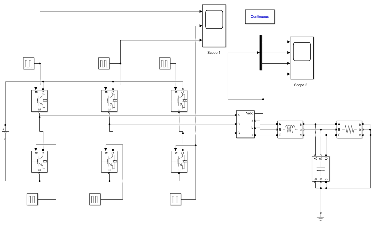
Figure 1. A Simulink model of a DC to AC Voltage Source Converter with a Pulse Width Modulation (PWM) block used for control.
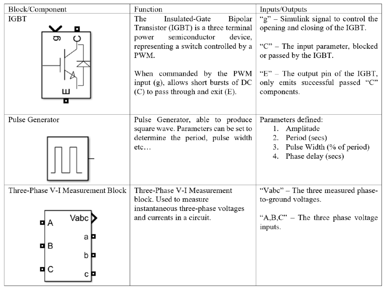
Six insulated-gate bipolar transistors (IGBT) are used in conjunction with six pulse generators, that mimic a three-phase pulse input, to allow both passing and blocking of the DC voltage. As the pulse generators
VSC Simulink Blocks
Simulink PWM Design
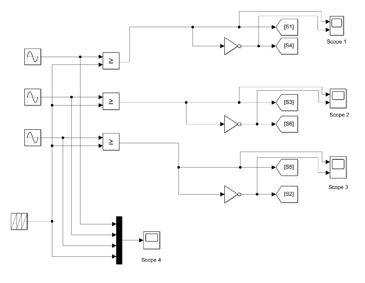
Figure 2. A Simulink model of a six output pulse generator, utilising mimicked three-phase input produced by 3 sine wave generators.
This PWM was designed to provide a deeper understanding of the role played by the pulse generators, which are the standard block provided by the Simulink software.
ABC to D-Q Reference Frame Converter
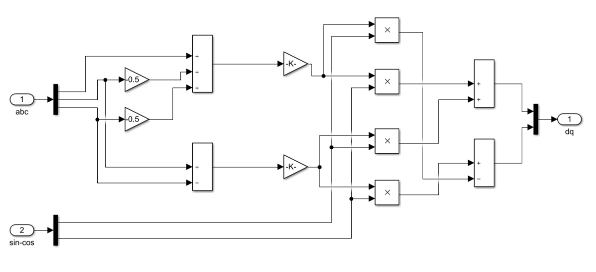
Figure 3. A Simulink model of a designed Reference Frame Converter, utilising matrix multiplication. The K gain values represent the matric multiplications and the summation blocks denoted by X are for the matric multiplication between the alpha/beta components of -sin and cosine taken from the Phase Locked Loop in Figure 4.
A key benefit to Soft-Open-Point voltage converters is the active and reactive power controls managed by the PI controllers, however it is well documented that designing a PI controller in Simulink capable of determining these power controls from three-phase inputs is challenging. To overcome this complication, an ABC to D-Q reference frame converter, is used to compare reference Idq currents to actual Idq currents to generate an error signal. this error signal is then forwarded to the PI for retroactive power control management.
The reason for this conversion is as follows: The three phase components of the SOP are represented by time varying differential equations, which makes controller design difficult. These three phase components of the SOP can be decomposed into two orthogonal axis variables, altering them into linear equations that can be easily controlled through standard PI controllers. The Clarke transformation is used to convert ABC stationary three-phase sigals into stationary two-axis components, while the Park transformation rotates these two-axis frame at the same speed as the electrical frequency, so turning AC waves into steady DC values.
Next Steps
Now the ABC to D-Q reference frame converter, Outer Power Loop, Current Control Loop and Phase Locked Loop can be designed. These are presented below:
Outer Power Loop
The Outer Power Control Loop utilises PI controllers to generate reference values for both Id and Iq, where the Id valuation is calculated with reference to the voltage cap and Iq with reference to the connected grid currents of the SOP.
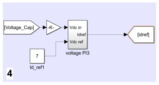
Figure 4. Simulink model for Voltage Cap Idref component of the Outer Power Controller based on P-Q Scheme.
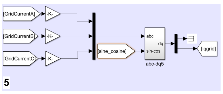
Figure 5. Simulink model of GridCurrent ABC component transformation into D-Q reference frame.
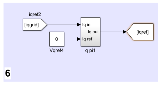
Figure 6. Simulink model of D-Q GridCurrent components and Vqref of 0 utilised as inputs for PI controller with output of iqref.
Current Control Loop
The Current Control Loop generates the three-phase sine waves utilised by the PWM to produce the pulses that control the operation of the IGBTs within the back-to-back VSC. The operation of the Current Control Loop is as follows:
The measured three-phase current values labelled as Iabc VSC1 in the VI measurement block B1 of Figure 7 are converted into d-q axis components through the Simulink circuit displayed in Figure 3 utilising the sine and cosine components of the PLL (Figure in Thesis Report).
The d-q axis components of the measured current IabcV SC1 are compared to the idref and iqref components generated within the current PI block. These comparisons summate the reference signals idref and iqref with the d-q components of the actual current measurements to form a singular d-q error signal output. This d-q error signal output is converted into its abc reference frame components using an inverse circuit of Figure 3.
These new error abc components are split using a Simulink Demux block into three distinct Sine wave channels that are used to control the PWM pulse generation. The Current Control Loop is displayed in Figure 8.
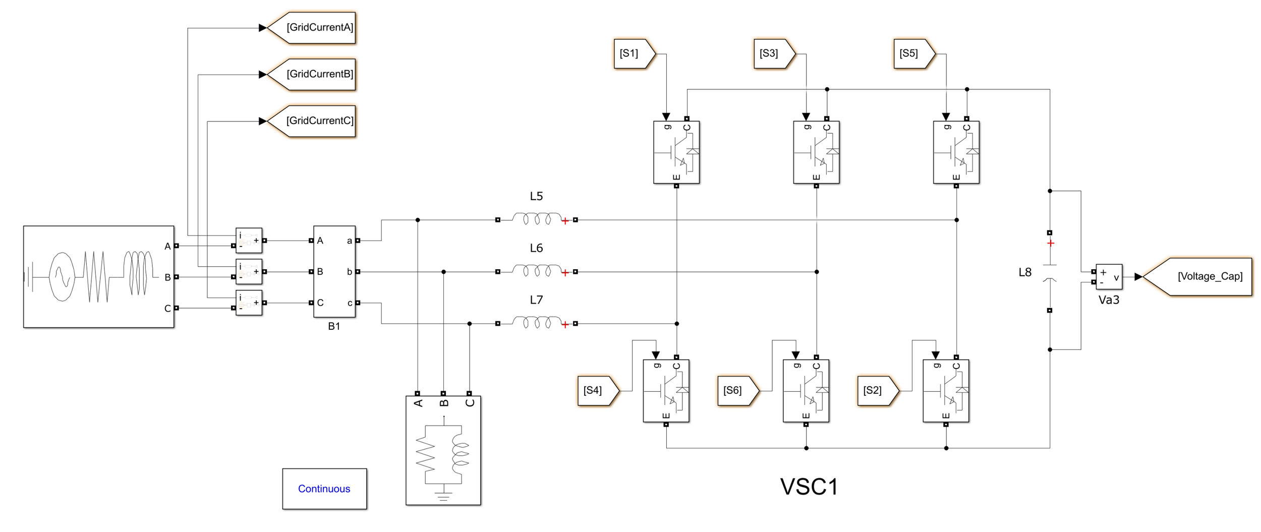
Figure 7. Simulink model for a back-to-back VSC utilised for the design of Current Control Loop Components.
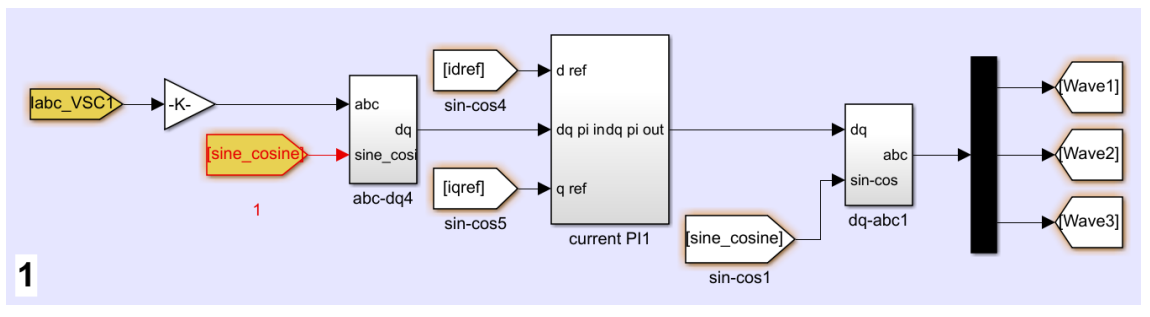
Figure 8. Simulink model of the Current Control Loop.
Phase Locked Loop
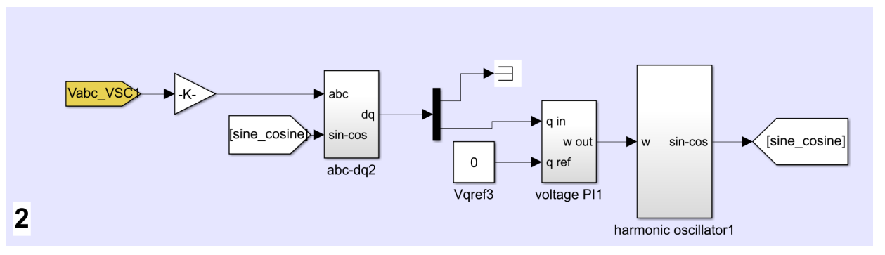
Figure 9. Final Simulink model of Phase Locked Loop based ABC to D-Q reference frame converter.
Final Simulink VSC Design
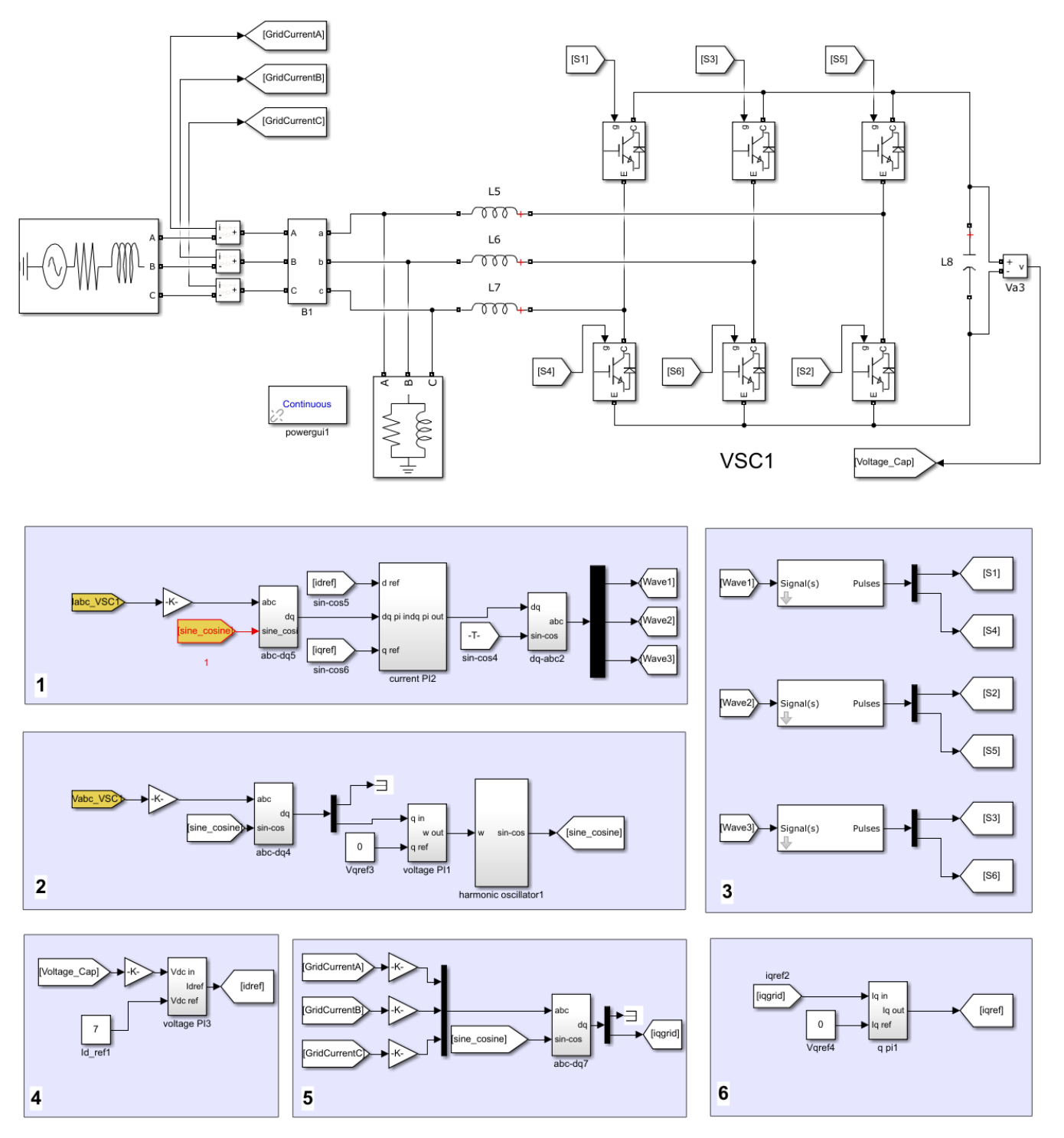
Figure 10. Simulink model of the Back-To-Back VSC, all parameters for this model can be found in the Thesis.
Conclusion
This page has summarised the 50 page document, available for download below, of the design and testing of a Soft-Open-Point Back-To-Back Voltage Source Converter, for further information please refer to the entire Thesis below.
Thesis Download
References
[1] Wanyu Cao, Jianzhong Wu, Nick Jenkins, Chengshan Wang and Timothy Green (2016). Operating principle of Soft Open Points for electrical distribution network operation, Applied Energy Journal, 184, pp.245-257