Fusion Materials - Design & Build a Tensile Magnetic System
This project, forming part of my MSc at the University of Bristol, gave me the opportunity to utilise my engineering experience to design and perform tensile tests on P-91 Steel, Stainless Steel & Inconel 718 alloys, to measure their suitability in upcoming national fusion programmes. This opportunity took place over the course of several months, and ended with a written dissertation, submitted to the University of Bristol, outlining my projects concept, design, methodology, results and conclusions. Throughout this page I have highlighted some of the key aspects, including background information on the project, how the test was designed and the subsequent results. Photos were taken during the process and thanks must be awarded to my professor and supervisor: Professor Mahmoud Mostafavi & Mehdi Mokhtarishirazabad.
-
Researching the means to create an inexhaustible source of clean, large scale, energy for the continued growth of mankind is arguably the top long-term priority for humanity. When considering the global concerns regarding: (i) increasing energy demand due to rising population levels, (ii) rising global sea levels and temperatures, (iii) the inevitable depletion of existing fossil fuel deposits and (iv) political issues arising with the use of fossil-fuels and present-day nuclear power, the argument for continued nuclear fusion research becomes clear.
Solving the exponential energy crisis as the world collectively develops and becomes more energy intensive will ensure humanities continued ability to flourish technologically and culturally without concern for large energy consumption. Intensive industries aimed at reducing our growing carbon footprint such as electric arc furnaces for steel production and desalination plants for agriculture will require high yield, low carbon energy. The process of nuclear fusion has significant advantages over its competitor nuclear fission, notably the risk of severe accidents like those at Chernobyl and Fukushima Daiichi which led to cancer increases among the population, and the radioactive waste produced by fusion is calculated to be smaller than that of fission plants.
Producing this near inexhaustible source of low carbon energy, following the example noted in of a Deuterium and Tritium reaction producing an energy of 17.6MeV with each fusion event, requires several technological challenges to be overcome before successful commercial operation of a plant can commence. For the above example of a Deuterium and Tritium reaction to occur: “the two nuclei must have enough energy to overcome the repulsive Coulomb force acting between the nuclei and approach each other sufficiently close that the short-range attractive nuclear force becomes dominant”. This repulsive Coulomb force between the nuclei is overcome through the heating of said nuclei to temperatures in excess of 5 ∗ 107K, it is this extreme temperature that produces the plasma which must be confined.
The issues associated with this plasma are as follows: (i) plasma confinement, (ii) reactor materials, and (iii) heat removal. The challenge focused on in this dissertation is the material selection for the plasma confinement chamber used in fusion plants. The materials required to build a plasma facing wall, designed to protect the magnets which produce the toroidal and poloidal magnetic fields, need to be survivable against high temperatures and have low neutron irradiation properties. Because of these requirements, low neutron activation steels are being examined in this dissertation for their suitability in plasma confinement chamber walls.
-
The physics involved in plasma confinement chambers is not the focus of this project, however it will be noted briefly the reasons as to why the physics of plasma itself causes great issue when choosing a suitable material for the walls of its confinement chamber. The environment produced to confine plasma as stated above is one of a strong magnetic field, this requires us to examine the effect the electromagnetic fields have on the structural components. In addition to dealing with the high electromagnetic field, the materials used to line the wall of the confinement chamber are also subjected to “high particle and neutron flux and high heat loads” . The materials chosen for this dissertation, outlined below, are solely chosen to test their change in material characteristics whilst under the influence of a magnetic field, as such the concern regarding their change in material behaviour whilst under heavy neutron bombardment and subsequent irradiation is not considered.
The materials must have a “high thermal conductivity for efficient heat transport, high cohesive energy for low erosion by particle bombardment and low atomic number” . Such materials used in this dissertation emit these qualities, the Nickel Alloy 718 has a high thermal conductivity of 9.3 – 11.5 W/mK at room temperature and P91 Steel has a high thermal conductivity of 26 W/mK at room temperature.
The magnetic field produced by the reactor’s confinement chamber is designed to stop the very hot plasma from being quenched when in direct contact with an ordinary container wall. It is for these requirements, to preserve the critical temperature for significant fusion yield, which must surpass the Lawson parameter, and with the “product of density and confinement time” being critical for this successful fusion ignition, we can outline the parameters of this dissertations experiment, focusing on the magnetic field effects of the structural materials.
-
This project, as a continuation of the work already commissioned by UKAEA and completed by University of Bristol Technical Specialist Mehdi Mokhtarishirazabad, uses the same tensile samples. Produced by the University of Bristol Engineering Workshop. These samples are in accordance with the agreement made between the UOB and UKAEA, they had a gauge length to gauge diameter ratio of 3 which meets ASTM-E2714.
To measure the extension in gauge length of each sample, a video extensometer (RTSS by LIMESS) was required, which monitors the difference in length between two markings. The process by which the vide extensometer deciphers these two markings is as follows: The sample is painted in a bright white coating, and two markings are made that create sharp black rings around the sample. The contrast between the white paint and the black marking is noted on the video extensometers mono-chromatic filter. Using an algorithm it notes the change in grey shading on the sample and can calculate where a sharp edge is, using this sharp edge the video extensometer can lock onto the two markings of the sample and record the extension between these two markings as the tensile test is undertaken.
By using the video extensometer a fast strain measurement could be taken with the camera operating at a peak framerate of up to 500Hz. The sample markings were 11 measured beforehand and noted as being 4.5mm for each sample, however due to problems during sample preparation some samples had different marking distances with an error of plus 0.5mm.
To create the white surface and two black markings on the samples, the sample gauges were painted with a layer of matt white high temperature primer (VHT SP118). To protect the threaded ends of the samples, to avoid issues when inserting into the accurately machined parts of the tensile rig, masking tape was applied to the ends of each sample. The sample were then mounted into a Dremel 3000 rotary tool and rotated with a speed of 10000 rpm, the VHT paint was applied using an airbrush. With the sample now coated with a uniform layer of the VHT paint. Two dots were created to show the bare metal of the sample using Vernier Calliper. A piece of dental floss was stripped to small individual strands, these strands were held by the student and applied to the sample on the marked dots whilst the sample was spun in the Dremel 3000. The application of pressure from the dental floss strands removed the layer of VHT paint, revealing the dark metal surface of the sample in a ring shape. The distance and quality of these sample markings were checked using an Optimax microscope. The advantage of using this type of paint is even after deformation during tensile testing, the markings retain their clarity for the video extensometer, allowing for continued recording of gauge length extension.
Test Design
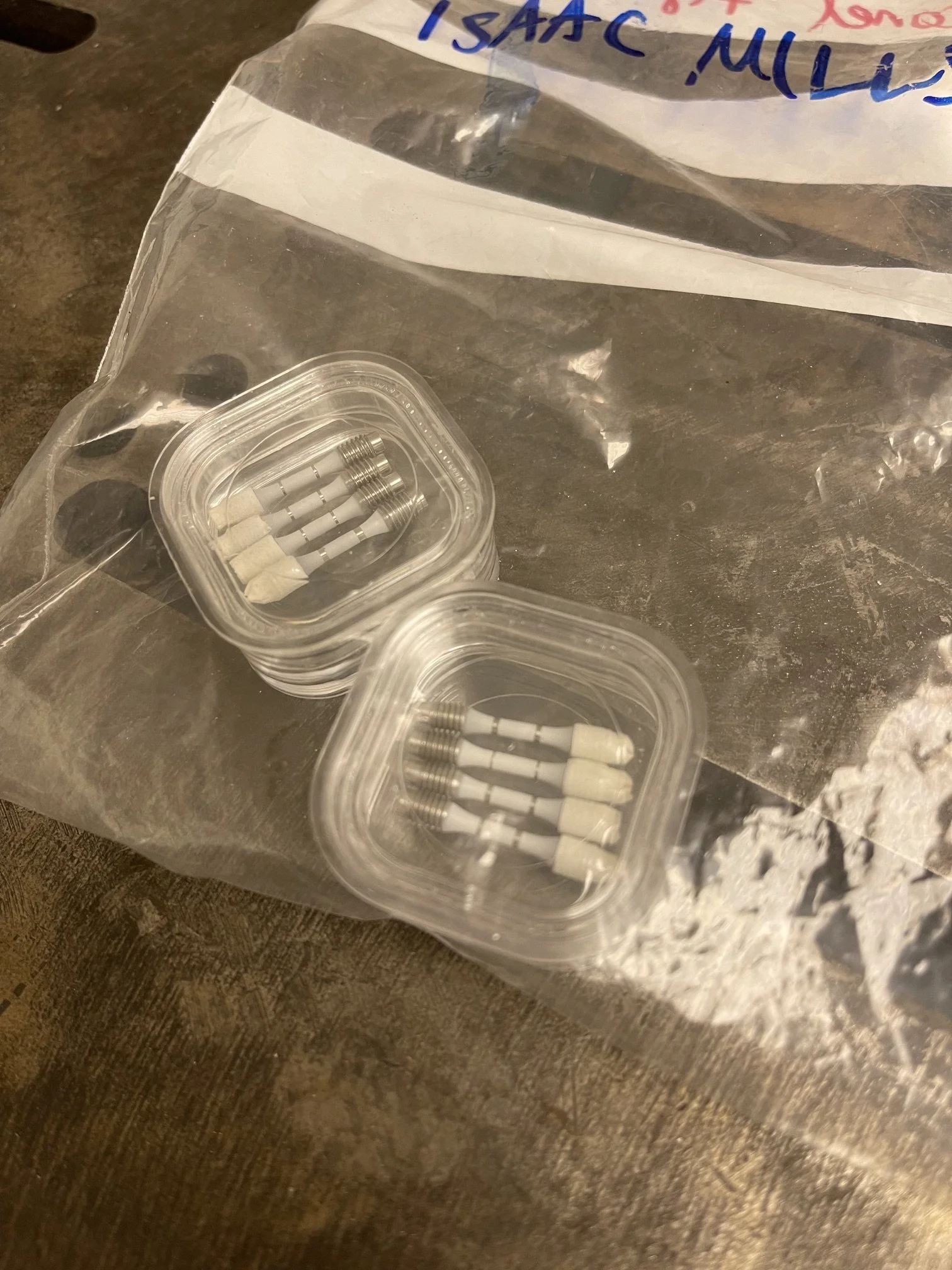
Figure 1. Two display cases containing 8 prepared samples of P-91 steel, having already undergone the primer coating phase of preparation these samples are ready for testing.
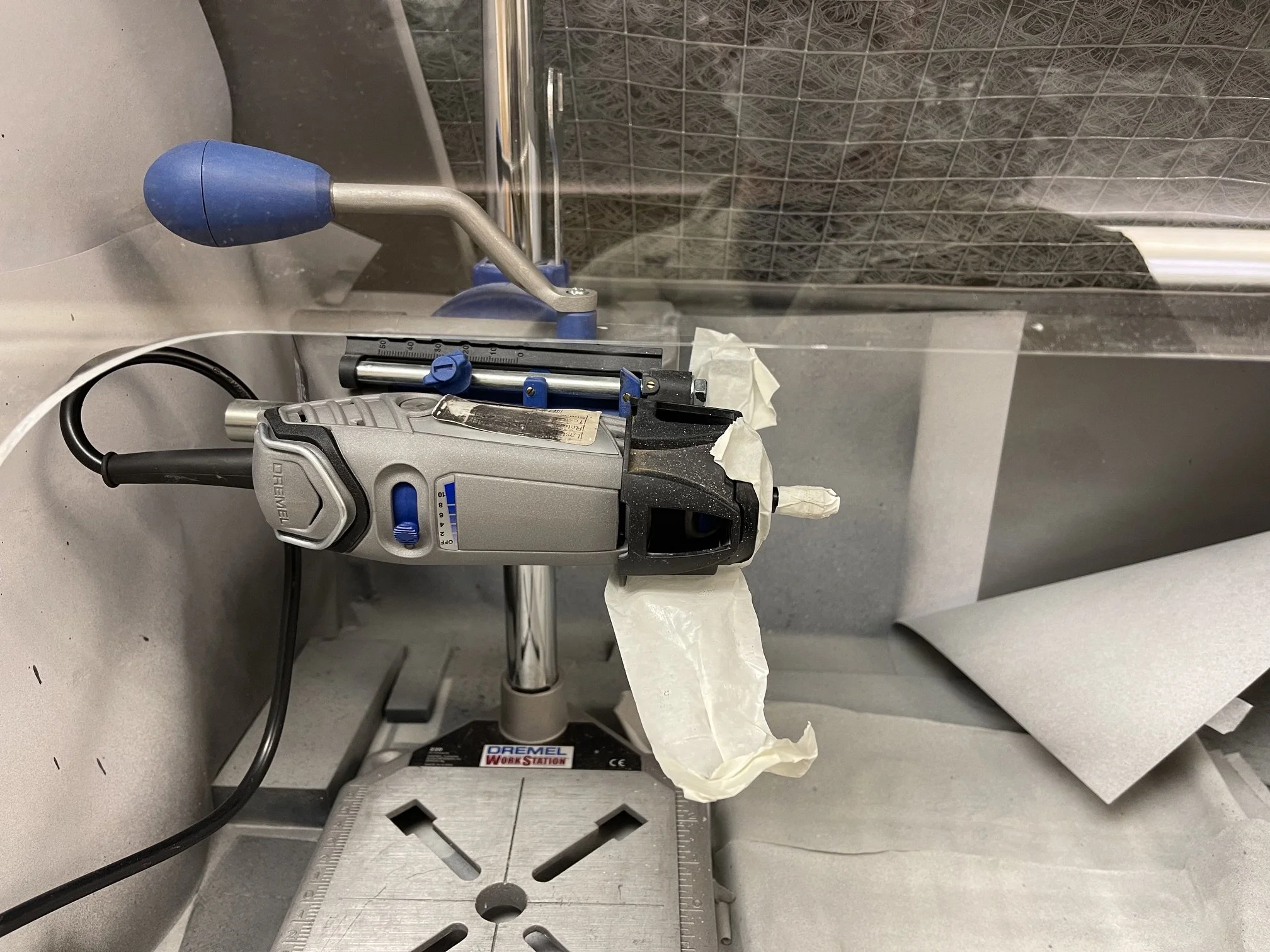
Figure 2. The samples were rotated in this spinning hand drill, to provide accuracy when using the dental floss to etch the two small notches into the primer.
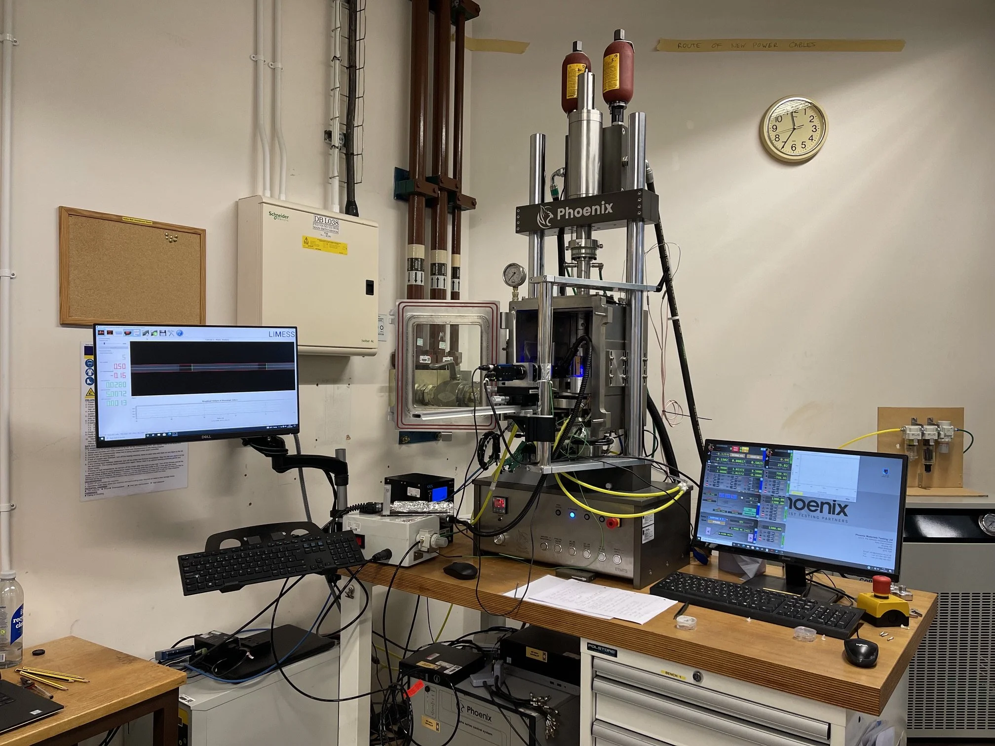
The samples of P-91 steel, shown in Figure 1, were to be used in a Phoenix Tensile Testing Bench (provided by the University of Bristol), the preparation of the samples was as follows:
Samples of P-91 steel are painted with a white VHT primer,
Check the finish under the Optimax microscope
Use a calliper was to create two small notches into the paint with a distance of 4.5mm Figure 2.
The sample was inserted it into the tensile machine without further adjustments.
After the tensile sample has been installed, the video extensometer is positioned correctly, with the light box and camera turned on
Then using a black gel pen I create two straight black lines on the sample at the notches
Once the lines are drawn the video extensometer is used to check the quality of the ink and if a reasonable measurement can be taken the sample is used
If however, the video extensometer does not pick up the change in grey scale accurately, the sample is removed from the tensile testing rig and taken back to the preparation zone for a second attempt.
Testing Equipment
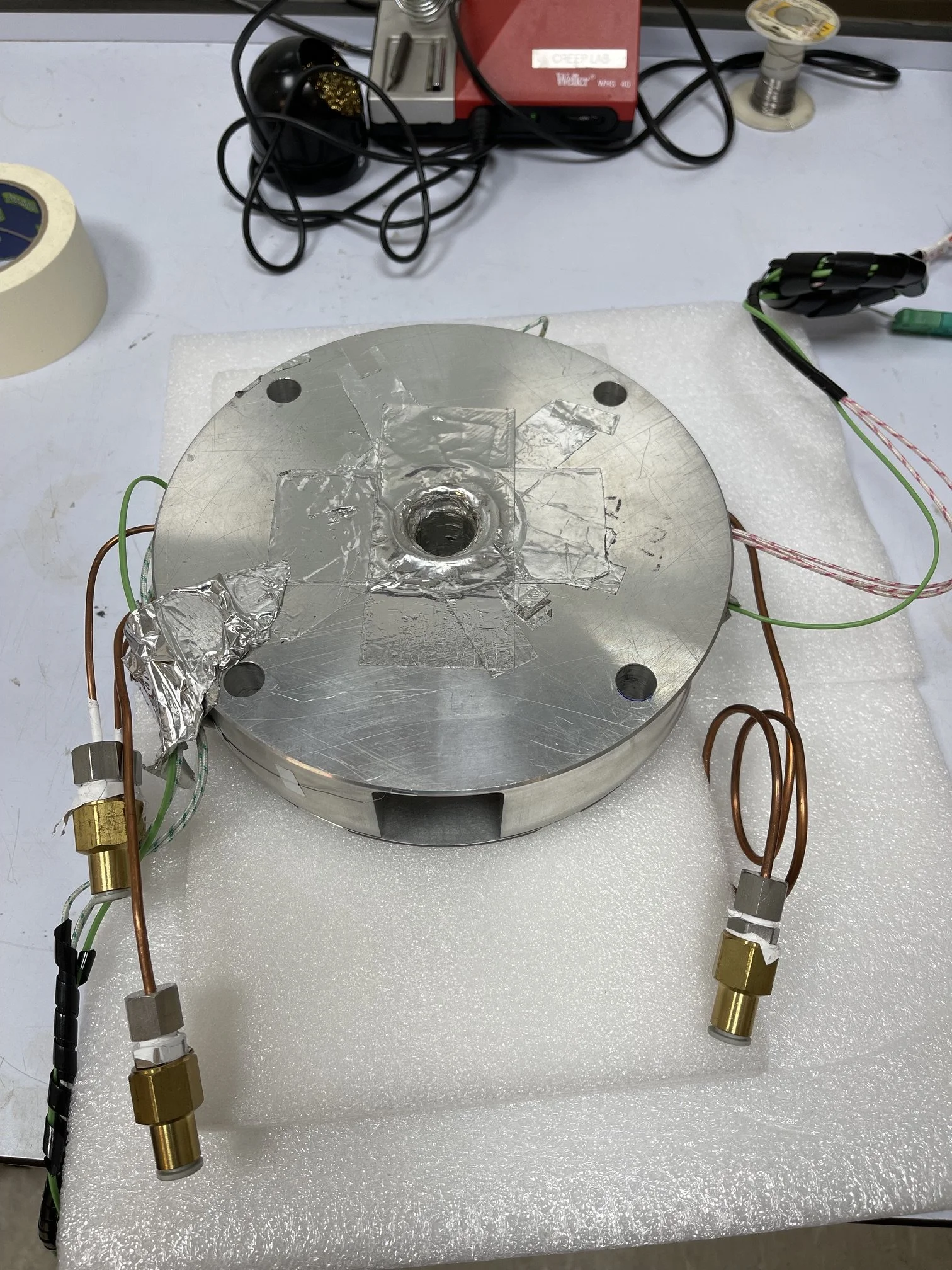
Figure 3. The Halback Magnetic Array designed to create a magnetic field perpendicular to the test sample.
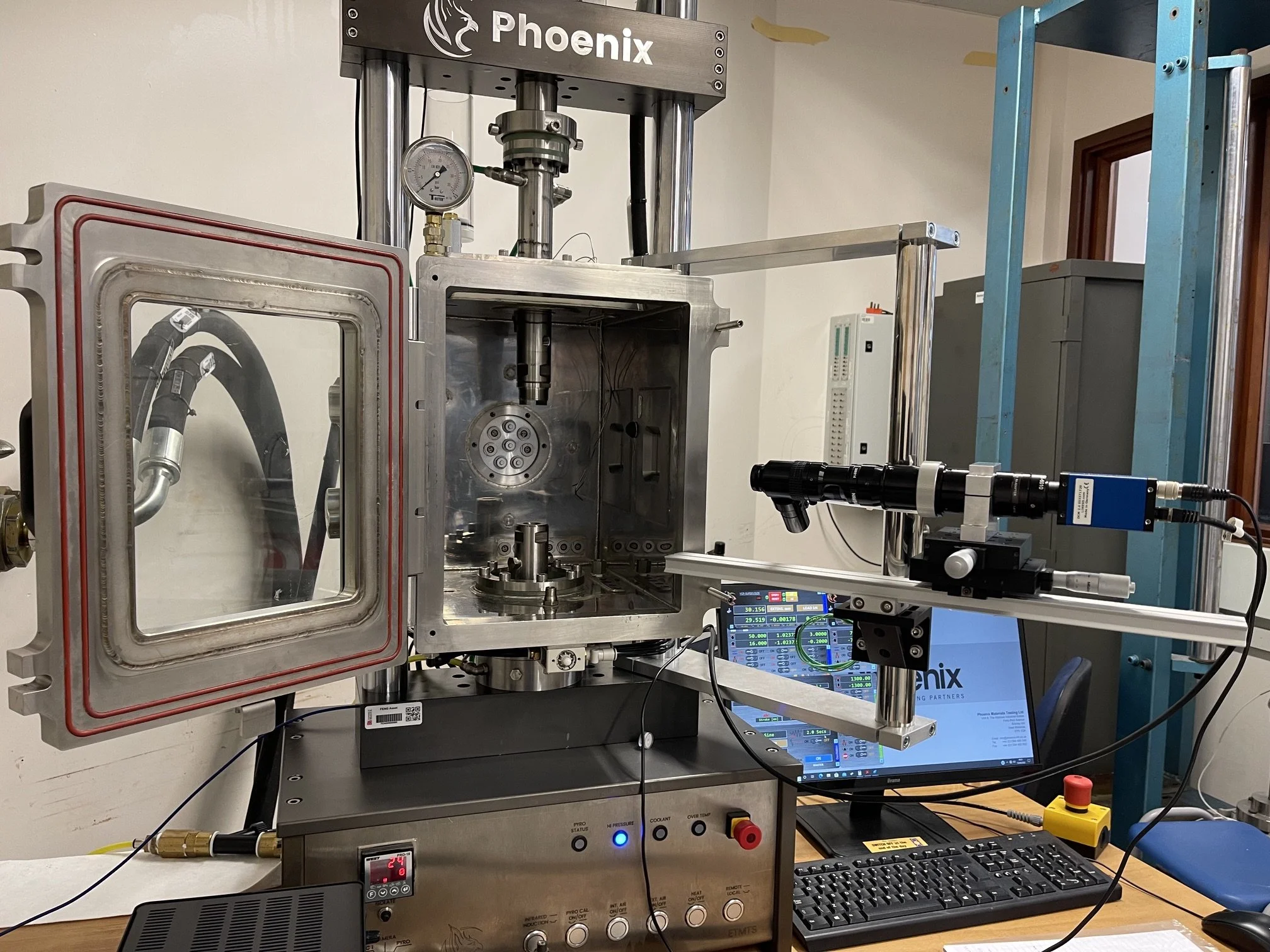
Figure 4. The Phoenix Tensile Testing Bench, with the assembled camera for capturing the failure of the P-91 sample.
Test Procedure
1. Hydraulics were warmed up using the Phoenix test bench by performing load free (displacement controlled) oscillation for 5 minutes.
2. Once warming up of the hydraulics had been completed, the loadcell was zeroed and the sample was mounted.
3. If the test had a magnetic field applied to the sample, the magnet at this stage would be lifted by the student and fixed in place by the tightening of metal grips on four support poles placed through the magnet. Creating an up and down axis of movement for the magnet. (If conducted without magnet this step was ignored.).
4. The Video Extensometer was positioned, the LED light was powered on.
5. Calibrated template for the using of lens was opened in the Video Extensometer PC, marks were located and the VE measurement was engaged. This recorded both images and data.
6. Load and displacement data were synced with the VE program, the sample extension, load and crosshead displacement were recorded in one fie on the Video Extensometer PC.
7. After the sample failed or reached a recorded total load value of 35 percent maximum load, the test was stopped.
8. Video Extensometer light was turned off and the VE returned to its position on the side of the rig.
9. Load on the sample was reduced to zero using loadcell software.
10. Sample was removed from the rig.
11. Hydraulic system was turned off.
Inconel Results
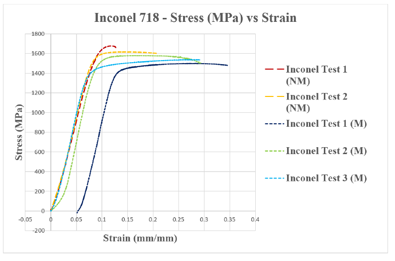
Figure 5. 5 samples of Inconel tested, two with no magnet present and three with a magnet present.
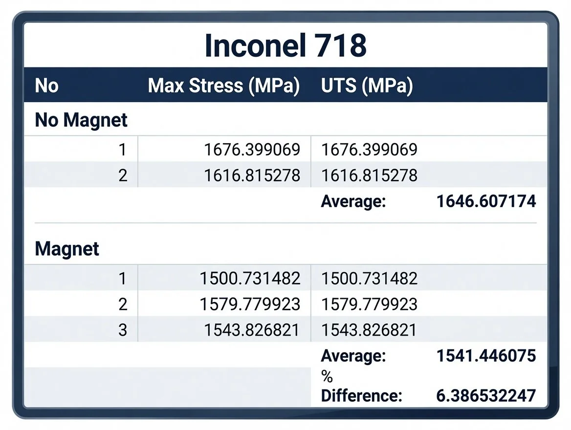
Table 1. Ultimate Tensile Strength calculations for Inconel samples, averaging the maximum stress each sample endured and calculating the percentage difference.
Figure 5 is a graphical representation of the five tensile tests conducted on Inconel, two of which had no magnetic field present and three which did. They are noted by the dotted line and (M) for the magnetic tests and the dashed line and (NM) for the non-magnetic tests. Due to concerns with the time taken for each tensile test to complete to the point of necking and breaking, the five Inconel tests are of differing length, denoted by the difference in their final strain value.
It should be noted from this graphical representation that Inconel Test 1 (NM) suffered from a error with the Video Extensometer software, leading to a misreading on the two marks and subsequent loss of the extension. With the loss of reliant extension data the hydraulic rig was stopped, the load reduced to 0 and the sample removed.
The average Ultimate Tensile Strength, which is defined as the maximum stress that a material can withstand while being stretched or pulled before breaking, is recorded for the Inconel samples both with and without a magnet present in Table 1. Unlike the graphical represent of Figure 5, the mathematical average allows for an easier deduction of the difference the magnetic field has on the material properties of the Inconel. With a noted reduction in UTS of 6% between non-magnetic and magnetic testing it can be argued that the presence of the magnetic field has reduced the structural suitability of Inconel.
Stainless Steel Results
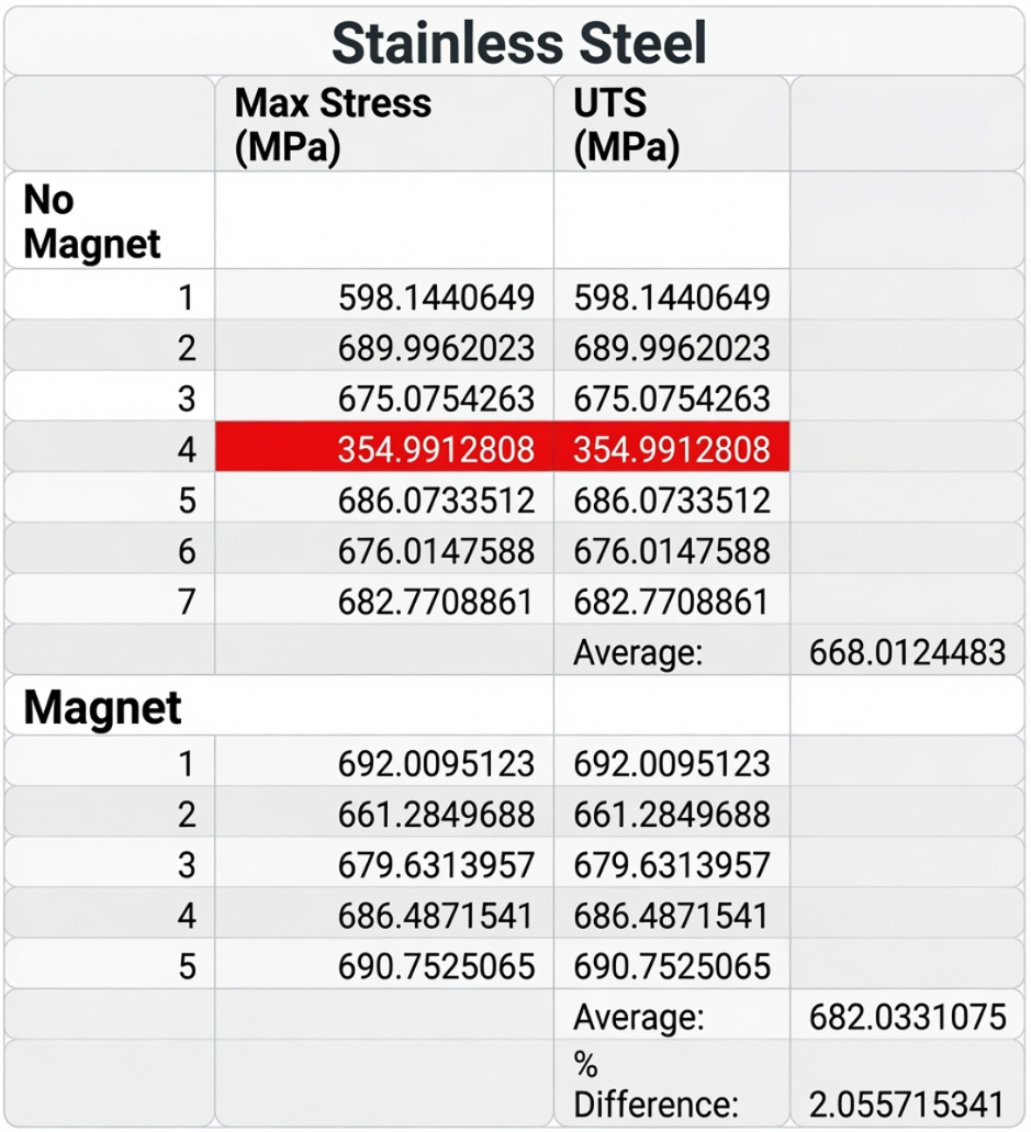
Table 2. Ultimate Tensile Strength calculations for Stainless Steel samples, averaging the maximum stress each sample endured and calculating the percentage difference.
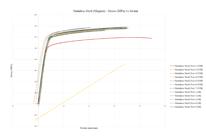
Figure 6. All 12 samples of Stainless Steel tested, 7 with no magnet present and 5 with a magnet present.
With a larger sample size for stainless steel compared with P91 and Inconel, the results are represented in Figure 6. Figure 6, which represents the non-magnetic tensile tests Stress vs Strain, has an anomaly of (Stainless Steel Test 4 (NM)) which can be attributed to a failure to properly record the initial load (kN) and displacement (mm) the sample was undergoing due to the Phoenix Tensile rigs clamps before the actual tensile test had begun. This data set has been omitted from further manipulation.
Table 2. Displays the UTS values for the stainless steel non-magnetic and magnetic tests with the 4th test omitted due to reasons stated previously, shows a small increase in percentage difference. With a higher UTS for samples with the magnetic field present.
P-91 Steel Results
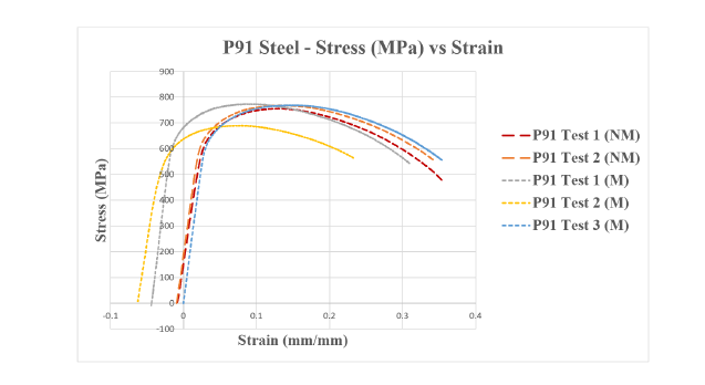
Figure 7. Five samples of P91 Steel tested, two with no magnet present and three with a magnet present
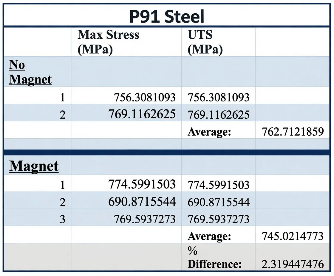
Table 3. Ultimate Tensile Strength calculations for P91 samples, averaging the maximum stress each sample endured and calculating the percentage difference
Similarly to the results shown in Figure 5, the P91 steel material had 5 available samples for use in this experiment. Figure 7, 2 for non-magnetic testing, and 3 for magnetic testing. The negative starting values for the samples can be explained by possible incorrect recordings for the displacement caused by loaded tension by the Phoenix testing rig.
This is another example of the human error that has effected the sample, and with a larger data set these risks would be mitigated. Table 3. displays a noticed drop in UTS when a magnetic field is induced perpendicular to the loading direction of the sample. Giving possible direction of a change in material properties that may make P91 steel less suitable for use in plasma confinement chambers due to the presence of a strong magnet field.
Conclusion
Despite this project developing several issues in the early stages of planning, including the limited supply of Inconel, the issues with manufacturing the Inconel samples correctly and the problems with the finish on the P91 steel samples reducing students ability to properly prepare the samples for use with the Video Extensometer. All of which contributed to the reduced scope from: Non-magnetic and magnetic tensile and creep tests at both high and room temperature on 15 samples of P91 Steel and 31 of Inconel 718. To a non-magnetic and magnetic tensile tests at room temperature on 5 samples of P91 Steel and Inconel 718 with additional tests on Stainless Steel 316. The results delivered were in support of the findings from the referenced document . The reduced ultimate tensile strength of 2.31% for P91 steel and 6.38% for Inconel 718 provide ample evidence for the need to continue research in this field to understand the micro-structural changes occurring in the metals when in the presence of a magnetic field. Understanding these changes will help us better assess the suitability of the metals for use in fusion reactor plasma confinement chambers.